MIT
4.202 Geometric Modeling Fall 2003
3D Modeling in AutoCAD - Supplemental Handout
prepared by:
Haldane Liew
version: 2003.10.10
3D AutoCAD Basics
Viewing
3D Orbit
The easiest way to view in 3D is to use the 3dorbit command
or the 3d Orbit toolbar. Right-click in 3dorbit mode gives you options on
projection, shading and some other visual aids.
Shading
To change the way AutoCAD changes the shade mode, use the shademode
command or the Shade toolbar.
Viewports
Use the vports command or the Viewports toolbar to split
your screen into multiple views.
Views
After creating a view, you may want to save it. Use the view
command or the View toolbar to save your views. The View toolbar also provides
icons for some predefined views. The elevational views alter the ucs. The
isometric views do not. The plan command can change the current
view of the drawing so that it is perpendicular to the current ucs or the
wcs.
Coordinate Systems
WCS - World Coordinate
System
A coordinate system used as the basis for defining all objects and other coordinate
systems.
UCS - User Coordinate
System
A user defined coordinate system. The user can only draw on the xy plane
of the current UCS. To draw on another plane, the UCS must be changed.
To alter the UCS, use the ucs command.
UCS command
The ucs command comes with many options but some of the more useful ones are
3point, origin and world. 3point defines
a new ucs given 3 points which correspond to the origin, a point on the x-axis,
and a point on the y-axis. Origin moves the origin point (0,0,0) of the UCS
to the designated point. World changes the UCS to match the WCS which is commonly
used method to reset the UCS.
UCS icon
The ucsicon command controls how the ucs icon is displayed
on the screen.
Solids
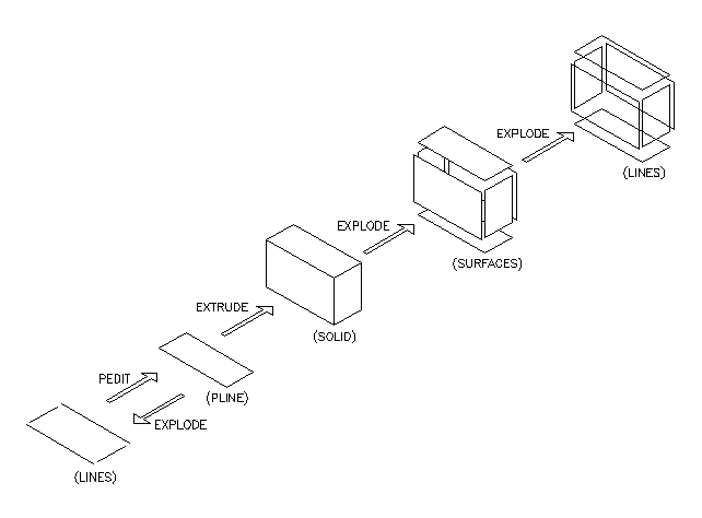
Extrude
The most common method to create solids is to use the extrude command and
extrude a solid from a closed pline. The original pline will become the new
solid which will be created on teh current layer. A couple of things you should
be aware of when doing this: 1) Make sure all your corners are closed by using
object snaps. If the pline is not closed, the extrusion will not work. 2)
Make sure the pline does not overlap itself. This will generate solids with
extra lines and have potential problems when exporting to other programs.
3) If, after all your efforts to fix a pline, it still doesn't work, it's
usually best to start over and trace a new pline.
Solid Display
Sometimes a solid in AutoCAD looks like a bunch of lines as opposed to a solid
object. To increase the number of lines used to represent a solid, use the
isolines command and increase the number. The higher the
number, the more lines used and the longer it takes to display the object.
Solid Editing
Union, Subtraction, Intersection, Slice, Revolve, with the Solid and Solids
Editing toolbar.
Relationship between LINES, PLINES, SOLIDS, and SURFACES