MIT
4.202 Geometric Modeling Fall 2003
Using MAX: Geometry, Cameras and Lights - Hands-On Handout 1
prepared by:
Haldane Liew
version: 2003.10.24
This handout provides a step-by-step process to make your first renderings with
MAX. It only covers a few of the most commonly used commands that you will need
for your assignment. For a more detailed explanation on the interface and tools
of MAX, refer to the lab handouts and the Help menu in MAX.
Import Geometry
01. Import an AutoCAD model into MAX.
File>Import
Select DWG format in
the file type, and browse to locate the file you just downloaded (3d_citrohan_10_bottom01.dwg).
Import the file.
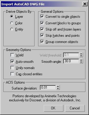
Select "Completely
replace current scene", click "OK" and an "Import AutoCAD
DWG File" window should appear.
In "Derive Objects
By" section, select "LAYER"
In "General Options"
section, select all options.
In "Geometry Options"
section, select "Auto smooth" only. Leave the "Smooth-angle"
at 30.
Type "0.01"
for the surface deviation in the ACIS option.
Your "Import AutoCAD
DWG File" window should look like this.
Click "OK".
Save your current MAX
file (File>Save As...)
Views
02. Maximize the Top viewport.
To switch between 4 viewports
and 1 viewport, hit "alt+w" on your keyboard or click on the
Min/Max Toggle icon.
Make your screen have
one big viewport.
To change the view to
be the Top view, type "t" on your keyboard or right-click on the
name of the viewport and select Views>Top.
Change your view to the
Top view.
Object Wireframe Color
03. Change the wireframe color of an object.
Use the
"Region Zoom" icon to zoom in on the stairs.
Click on the
Select icon to go into selection mode.
Click on the stairs.
In the command panel,
click on the "Modify"
tab.
Click on the color swatch
next to the name of the object to change its color.
To see the change in
color, deselect the stairs by clicking in an empty area or ctrl-click on the
selected item.
Camera
04. Create a camera.
In the Top view, click
"Zoom Extents"
to see all the objects.
In the command panel,
select the "Create"
tab and click on the camera
icon. Click on "Target" to create a camera with target control.
Click and hold the mouse
button in the Top viewport to set the location of the camera, and then drag
the cursor to set the location of the camera's target. The camera and target
will be set when you release the button.
To go back to selection
mode, click on the Select
icon.
Make 4 viewports by typing
"alt+w" or by clicking on the
Min/Max Toggle icon.
05. Select a viewport to show
the camera's viewpoint.
Click inside the perspective
viewport and type "c" on the keyboard.
or
Right-click on the viewport's
name and select Views>Camera01
06. Move the camera.
By default the camera
is created on the ground plane, so we need to move it up.
Set the selection filter
to "Cameras" so we can only move the camera without moving other
objects.
Click on the
Move icon.
In the Front or Left
view, select the camera or the target and move them up one at a time.
or
select the line connecting
the camera and target to move both at the same time.
07. Create a 2 point perspective.
To create a 2 point perspective,
the camera and its target have to be at the same height.
Click on the
Move icon.
In the Top view, click
on the camera to select it.
Right-click on the
Move icon. A "Move Transform Type-In" window should appear which
lets you specify precise coordinates (absolute and relative).
Type 1.5 in the "Absolute:World"
Z input field. This sets the target to be 1.5 units in the Z axis. In our
case that's 1.5 meters (eye level).
Close the window and
repeat the procedure for the camera's target.
08. Change the camera lens.
Select the camera.
Select the
"Modify" tab in the command panel.
To change the zoom factor
of the camera, click on a different "Stock Lenses" button or change
it manually in "Lens" or "FOV" (field of view) inputs.
09. Other types of views (axonometric,
elevation, section perspective).
To create a parallel
projection with the camera, check the "Orthographic Projection"
option under the "Parameters" rollout. To get an axonometric, make
sure the camera and target points are at different heights. To get an elevation,
make sure the heights are the same.
To create a sectional
perspective, check the "Clip Manually" option in the "Clipping
Planes" option under the "Parameters" rollout. Set the "Near
Clip" to be where the section begins.
Visualize
10. Render an image.
Click inside the camera
viewport to make it active.
Click on the
"Quick Render" icon.
Materials
11. Create a generic white material.
Open the material editor
by clicking on the
Material Editor icon.
Select any slot and give
this material a name (such as "white_material").
Click on the Diffuse
color swatch. A color selector will appear. Adjust the slider to make the
color white.
Close the color selector
window.
12. Assign the white material
to the mullions.
Click on the
Select icon.
Change the selection
filter to "All".
Select the mullion object
by clicking on it.
If you can not precisely
select the object, open the "Select by Name" window by clicking
on the
Select by Name" icon or by typing "h" on the keyboard. Highlight
the mullion object and click "Select".
Click the
"Assign Material to Selection" button in the Material Editor window.
Click inside the desired
viewport to activate it and then click on the
"Quick Render" icon to visualize the changes. Or press F9 to render
the last view.
13. Assign the white material
to all the objects in the scene.
Open the "Select
by Name" window.
Highlight all the objects
in the list by clicking "All" and then "Select".
Click the
"Assign Material to Selection" button in the Material Editor window.
The Material Editor will ignore objects, such as cameras and lights, which
do not have material properties.
Close the Material Editor
window.
Click inside the desired
viewport to activate it and then click on the
"Quick Render" icon to visualize the changes. Or press F9 to render
the last view.
Lights 14. Create a spotlight.
In the command panel,
select the "Create"
tab and click on the lights
icon. Click on "Target Spot" to create a spotlight with target control.
Click and hold in the
Top viewport to set the location of the light, and then drag the cursor to
set the location of the light's target. The light and target will be set when
you release the button.
To go back to selection
mode, click on the Select
icon.
15. Move the spotlight.
By default the light
is created on the ground plane, so we need to move it up.
Set the selection filter
to "Lights" so we can only move the light without moving other objects.
Click on the
Move icon.
In the Front or Left
view, select the light or the target and move them up.
Click
"Quick Render" to visualize the changes.
Ambient Light 16. Increase ambient light.
Open the Environment
window (Rendering>Environment...).
Click the "Ambient
Light" color swatch to open a color selector window. By default ambient
light is black (value=0). Move the slider to make it brighter.
Click
"Quick Render" to visualize the changes.
Set the ambient light
back to black.
Hide/Display 17. Hide the current camera.
In the command panel,
select the "Display"
tab.
In the "On/Off"
rollout menu, click on "Turn Off by Name...". Select Camera01 and
click "Off".
(To unhide the camera,
click on "Turn On by Name...")
18. Create another camera.
Set the selection filter
to "Cameras".
In the Top view, create
a new camera (same as section 03).
Change the viewport to
display the camera's perspective (same as section 05).
In any side view, move
the camera up to get a distant aerial view.
Click
"Quick Render" to visualize the changes.
Modify Light Properties 19. Modify the spotlight.
Click on the
Select icon.
Set the selection filter
to "Lights".
Select the source of
the spotlight.
In the command panel,
select the "Modify"
tab. The information on the current selected object will appear.
20. Change the color of the
light.
In the "Intensity/Color/Attenuation"
rollout menu, click on the color swatch to change the color of the light.
Try changing the color.
Click
"Quick Render" to visualize the changes.
Restore the color of
the light to white.
21. Change the intensity of
the light.
In the "Intensity/Color/Attenuation"
rollout menu, change the value of the "Multiplier" to change the
intensity of the light.
Try a value of 2 or 3.
Click
"Quick Render" to visualize the changes.
Set the "Multiplier"
value back to 1.
22. Activate shadows.
In the "General
Parameters" rollout menu, make sure the shadows option is checked. By
default MAX uses shadow maps which make fast but fuzzy shadows. To get sharp
shadows, you need to use another algorithm called ray trace.
23. Ray traced shadows.
In the "General
Parameters" rollout menu, under the "Shadows" section, change
the shadow type option to "Ray Traced Shadows".
Click
"Quick Render" to visualize the changes.
24. Shadow bias.
Change the "Render
Type" to "Blowup".
Click on the "Quick
Render" icon.
Click in the Camera viewport.
Manipulate the rectangle marque so that it covers just the area around the
corner of the building. Click "OK".
Notice there is a gap
between when the shadow starts and the object
In the "Ray Traced
Shadow Params" rollout menu, change the value of "Ray Bias"
to be a small number such as 0.01. A small number will make the gap between
the shadow and its object smaller. If you make the number too small, you might
begin to see strange artifacts. This rollout menu only shows up if you are
using ray traced shadows instead of shadow maps.
Click
"Quick Render" to visualize the changes.
25. Hotspot and Falloff
Select the light source
and in the command panel, select the
"Modify" tab. Open the "Spotlight Parameters" rollout
menu.
Change the Hotspot value
to 15 and the Falloff to 18. This changes the angle of the spotlight cone.
Change the "Render
Type" to "View".
Click inside the camera
viewport and click
"Quick Render" to visualize the changes.
Now change the Falloff
back to 45.
Click
"Quick Render" to visualize the changes.
Set the Hotspot back
to 43.
Click
"Quick Render" to visualize the changes.
26. Change light type.
Rename your light to
"Direct Light".
In the "General
Parameters" rollout, change the "Light Type" to "Directional".
In the "Directional
Parameters" rollout, change the value for Hotspot to 20 and Falloff to
22. Unlike spotlights, the numbers in hotspot and falloff for direct lights
indicate the radius of the cylinder.
Click
"Quick Render" to visualize the changes.
Check the "Overshoot"
option and rerender to see its effects.
Secondary Lights 27. Create an omni light.
When using only one light
source in a scene, all the surfaces that do not get direct light will be in
complete darkness. To be able to articulate the surfaces in shadow, we will
create a very dim secondary light to give those surfaces more definition.
Secondary lights should be very dim and cast no shadows.
In the command panel,
select the "Create"
tab and click the "Lights"
icon.
Select "Omni"
as the type of light.
In the Top view, click
once to set the location of the new omni light. Place the omni light in the
middle of the building.
In the Front or Left
view, select the omni light and move it up above the building.
Click
"Quick Render" to visualize the changes.
28. Make the omni light very
dim with no shadows.
Select the omni light
and select the "Modify"
tab in the command panel.
Uncheck the "On"
box in the shadows section.
Change the multiplier
value to 0.3 or 0.4.
Move the omni light above
the center of the building.
Click
"Quick Render" to visualize the changes.
Rendering Options 29. Image size.
By default, the image
size is set to 640x480 pixels.
Rendering>Render...
or click on the
"Render the current scene" icon.
In the "Common Parameters"
rollout menu, set the "Time output" to "Single" (unless
you're making an animation).
In the "Output Size"
section, set the image size by clicking one of the preset buttons or type
in a custom size.
If faces are disappearing
in your renderings, in the "Options" section, check "Force
2-Sided".
Select the appropriate
viewport.
Click "Render".
30. Save the rendered image.
After making a rendering,
click on the "Save"
icon in the Virtual Frame Buffer window.
Select an appropriate
file format (JPEG for the web and TIFF for printing/archving).
Save the file with the
appropriate name, location and format options.